Configurations
When the prerequisites are fulfilled, use the following steps to configure a site-to-site VPN on Secure Firewall:
Step 1. On your management center, navigate to Devices > VPN > Site To Site. The site-to-site VPN configuration page appears.
Step 2. From the Add VPN drop-down, select Firepower Threat Defense Device. The Create New VPN Topology configuration window appears.
Step 3. On the Create New VPN Topology window, name the VPN topology, select a network topology type, and choose the desired IKE version.
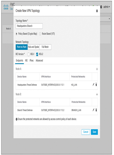
Figure 19-21 shows navigation to the site-to-site VPN topology configuration page. For this site-to-site VPN configuration, a policy-based point-to-point network topology has been chosen with IKE version 2.

Figure 19-21 Site-to-Site VPN Topology Configuration
Step 4. On the Endpoints tab, click the + icon to add the details of the Node A side of the configuration—the threat defense at headquarters site. The Add Endpoint configuration window appears.
Step 5. On the Add Endpoint window, select the threat defense and its interface. The interface IP address should auto-populate.
Step 6. Click the + icon on the Add Endpoint window to add the networks whose traffic will be protected through the VPN tunnel. If a desired network object is not predefined on the Objects > Object Management page, you can create it now on the fly.
Step 7. Click OK to return to the Create New VPN Topology window. Node A (the headquarters site) is configured at this stage.
Step 8. Repeat Steps 4 to 7 to add Node B (the branch site). Figure 19-22 shows the configurations of Node A and Node B.

Figure 19-22 Configuration of Endpoints in a Point-to-Point Topology
Step 9. After both nodes are added (see Figure 19-23), click the Save button to save the VPN topology.

Figure 19-23 Creation of a New VPN Topology with Two Nodes
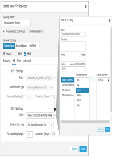
Step 10. If you deploy the configurations at this stage, both threat defense devices should be able to establish a site-to-site VPN tunnel between them. However, if you want to strengthen the VPN tunnel security, there are numerous options to configure in this Create New VPN Topology window. For instance, under the IKE tab, you can create your own IKEv2 policy with stronger security attributes and select it for your site-to-site VPN tunnel (see Figure 19-24).

Figure 19-24 Creation of a New IKEv2 Policy
If you configure any additional options for your VPN topology, don’t forget to save the configurations. Deploy the configuration changes on both threat defense devices by navigating to Deploy > Deployment.
When the deployment is successful, you are ready to test the communication between the headquarters and branch sites through the VPN tunnel. From one of the hosts in the headquarters, attempt to connect to a host in the branch site. If the hosts are able to communicate, that’s great. You can move to the Configuration Verification section to analyze the IPsec tunnel statistics.
If the hosts between the headquarters and branch sites are unable to communicate through the VPN tunnel, analyze the connection events and review any existing settings that may be blocking the traffic. The following sections help you to solve this issue.
Leave a Reply